The local building department inspector, aka the Authority Having Jurisdiction (AHJ) is the party with the final say regarding the National Electrical Code (NEC). The NEC is the primary document for regulating the installation of electrical equipment. As a Field Evaluation Body (FEB), our primary role is to evaluate equipment to its applicable equipment safety standard, but we must also be aware of the installation requirements of the NEC. One reason for this is that the demarcation of where the installation ends and the equipment begins can be fuzzy. In these situations, the FEB needs to be able to apply the most applicable requirements given the situation. In this Part II of our three-part article, we aim to give some guidance on NEC requirements that we have encountered while performing field evaluations on switchgear.
Cable Limiters:
In the current version (2017) of the NEC, solar/parallel power taps to the line side of the main service disconnect require cable limiters if the tap is made using more than 10 feet of conductor length to the solar fuse. This can be a tough requirement to meet; depending on where the parallel power conductors enter the switchgear enclosure, the amount of conductor in the switchgear alone may be 10 feet. The 2020 version of the NEC loosens this requirement for many installations. In the first scenario, it allows the conductor length to increase to 16.5 feet if the gear is located inside a non-residential building. In the second and most advantageous scenario, the 2020 NEC removes the limit on conductor length (i.e., no cable limiter requirement) if the gear is located outside of a building, see 705.11C (2020 NEC).
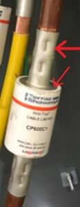
A fault on the service side of the main disconnect can be catastrophic, and although cable limiters offer protection against faults on this side of the line, they do have some short-comings. In addition to being pricey, cable limiters are big and may not physically fit in some gear. In these cases, an additional junction box may have to be installed to house them. In tight spots, cable limiters can be difficult to crimp. They also have bare live surfaces that are large and difficult to insulate as illustrated below:

When installing line-side taps outdoors or in commercial buildings, we recommend speaking with your plan check department to discuss the use of the 2020 NEC. If you can take advantage of this code’s relaxed cable limiter requirements; it could help to make the installation simpler and faster.
Even outdoors, a line-side fault can be problematic. Most faults in this particular application are likely to stem from conductor insulation being compromised during installation. We recommend after pulling all conductors from the PV disconnect into the main section and before interconnecting to the utility, conducting a high voltage insulation resistance test on the conductors from: phase-phase and phase-ground. This should help to reveal significant damage to insulation during the install. This is especially helpful for large conductors and/or longer runs.
Neutral Size:
In accordance with 705.95B of the NEC, neutral conductors of utility interactive inverters used solely for instrumentation or detection (i.e. not carrying current to/from the external load) can be smaller than the current-carrying conductors. These neutrals can be sized as grounding conductors. For long runs and large ampacities, this reduction in neutral size can save time and money. Since these neutrals are generally grounded by the time they interconnect to the service equipment, they should be tapped on the line-side of the neutral disconnect link (if one exists). This will help keep the neutral bus on the load side of the disconnect isolated from ground for testing and GFI purposes.
Line-Side PV Conductor Routing:
In accordance with 230.7 of the NEC, service conductors are not to be installed in the same raceway as other conductors. When tapping PV or other parallel sources onto the line-side of the service disconnect, they become service conductors. In addition, when the main disconnect is located in a switchgear section flanked by distribution sections, the routing of these line side PV conductors becomes a concern. A common interpretation of NEC section 230.7 mentioned above is that these tap conductors should only be run through adjacent distribution sections if they are in a separate conduit identified as containing live PV circuits. This or equivalent means of separation is recommended when running service conductors in close proximity to load-side feeder or branch-circuit conductors.
Load-side Parallel Power Tap:
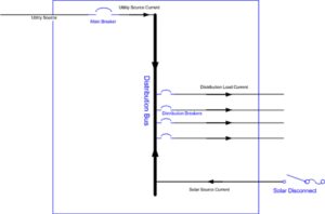
A bus tap can be used to provide parallel power on the load side of the service disconnect in lieu of a back-feed circuit breaker if for instance there is not ample space for an additional breaker. According to NEC 705.12B, when tapping or back feeding onto the load side, the sum of the current ratings of both source overcurrent protective devices (OCPDs) is allowed to exceed the current rating of the switchgear section bus by 20%. For example, say the switchgear section illustrated below is rated 800A; the sum of the overcurrent protection from the main breaker and the solar disconnect fuse can be 120% of 800A or 960A. If the main breaker is rated 800A (typically the factory main breaker is sized the same as the switchgear section) the fuse in the solar disconnect can be rated up to 160A. For this configuration the source of the solar/parallel power must be located at the opposite end of the distribution bus from the utility source. The reason for locating the parallel/solar source at the opposite end presumably is that when two synchronized voltage sources are located at opposite ends of a bus and the load is being drawn from the middle, the current supplied by each source cannot additively combine and potentially overload the bus. See Figure 1 below:

Fig. 1 – Power Sources Provided on Opposite Ends of a Distribution Bus
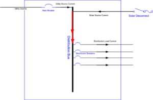
In contrast if both sources were located on the same side of the bus, the currents are likely to combine in an additive manner as illustrated in the Figure 2 below. This configuration could lead to overloading of the bus between the source connections and the load connections.

Fig. 2 – Power Sources Provided on the Same End of a Distribution Bus
The main problem with the load-side tap is that you are limited in how much power can be provided. In the example above the maximum fuse size for the solar fused disconnect is 160A. In accordance with the NEC 690.9, this fuse must also be sized no less than 125% of the maximum inverter output, which in this example allows for a maximum inverter output current of 128A. If an application arises where the amount of power doesn’t meet the intended requirement and a line-side tap is not an option, another potential solution is to downsize or de-rate the main breaker to make up the difference. In the example above the total sum of overcurrent protection between the main breaker and the solar fuse is 960A. If the main breaker is de-rated by 100A from 800A to 700A, this would allow the solar fuse size to be increased by 100A from of 160A to 260A, see table below. This is an alternate method to permit additional power from the solar/parallel interconnection.
Example Based on 800A Section – Total OCPD (Main Breaker + PV Fuse) = 120% of 800A = 960A
| Main Breaker Rating | PV Fuse Size | Inverter Max Output |
|---|---|---|
| 800A | 160A | 128A |
| 700A | 260A | 208A |
Adding New Service Section to an Existing Service:
If you are tapping on the line side of the existing main disconnect(s) to add a new switchboard section, this new section must be marked: “Suitable for Use as Service Equipment”. In addition, within this section or multi-section assembly there must be a main bonding jumper that establishes a return path from the main grounding bus to the supply neutral. Without this bonding jumper fault current from an insulation failure may not have a reliable return path back to the utility source, which could cause shock and fire hazards from fault current seeking unintentional return paths.
Field Evaluation Requirement (2020 NEC):
In accordance with 705.11(D) of the 2020 code, parallel power interconnections to the service side of the main disconnect(s) must either be done in accordance with the manufacturer’s instructions, i.e. the switchgear was designed to accommodate line side connections, or the modifications must be evaluated by a Field Evaluation Body (FEB). Since these line side taps are seen as modifications to existing UL listed equipment, many jurisdictions are currently enforcing the third-party FEB requirement, but it appears that it will also start to become a hard requirement from the code going forward.
To see our Part I article regarding UL equipment requirements for switchgear click on Part I (UL 891 Requirements). For more information on how we can assist with Field Evaluations click on Field Evaluation Service
For a quotation for Field Evaluation Services click Quotation


Comments are closed.